Home » Without Label » Mini Xlr Wiring Diagram / 3.5mm To Xlr Wiring Diagram - 10k resistor pin 3 to pin 4, 200pf capacitor pin 1 to pin 4, 200pf capacitor pin 2 to pin 4, crimp fingers to shield, use w5 type headset.
Mini Xlr Wiring Diagram / 3.5mm To Xlr Wiring Diagram - 10k resistor pin 3 to pin 4, 200pf capacitor pin 1 to pin 4, 200pf capacitor pin 2 to pin 4, crimp fingers to shield, use w5 type headset.
Mini Xlr Wiring Diagram / 3.5mm To Xlr Wiring Diagram - 10k resistor pin 3 to pin 4, 200pf capacitor pin 1 to pin 4, 200pf capacitor pin 2 to pin 4, crimp fingers to shield, use w5 type headset.. In addition, it may be helpful to label the wires prior to disassembly. The following xlr 4 pin wiring diagram photo have been authored. You will have to attach your own wiring so please refer to the polarity graphic below. Bridging 1&4 for signal, 2&3 for ground) 2. 5 pin & 3 pin xlr wiring pinout information.
Xlr to rj45 wiring diagram xlr electrical wiring diagrams. Xlr pin 1 = shield, amphenol pin 1. 5本 5,000円、10本 10,000円、15本 15,000円 5本から承ります。 Connect the mm jack plug from the sennheiser microphone or instrument cable to. Xlr to inch stereo jack plug.
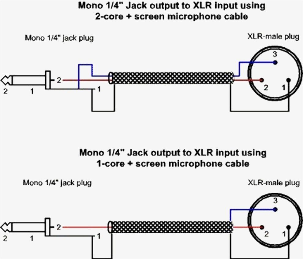
Xlr To Mono Jack Wiring Diagram | Wiring Diagram from annawiringdiagram.com Wiring diagram not only offers comprehensive illustrations of what you can perform, but also the procedures you need to adhere to whilst carrying out so. 5 pin & 3 pin xlr wiring pinout information. When connecting a 3 pin xlr to one rca you use the same wiring as if you were connecting an xlr to a 14 jack plug. The uninsulated ground wire should go to pin 1 the red wire to pin 2 and the black wire to pin 3. 3 pin xlr wiring diagram, cable wiring, etc. In addition, it may be helpful to label the wires prior to disassembly. For a mono output onto an xlr connector, you must use the following cables: Microphone madness dual xlr female to 1 8 3 5mm mm dxlrf 35sm.
It uses 4 shielded wires:
Connect the mm jack plug from the sennheiser microphone or instrument cable to. Xlr to 1/4 inch mono wiring diagram. Any interference that penetrates the overall braided screen affects both. If you use a bright light and look at the female connector (ta4f) used for.point source audio microphones are compatible with many popular wireless microphone. The pictorial shows the pin layout of a ta4f connector, as viewed from the wiring side. Replace your broken xlr connector or convert another type of battery charger to an xlr battery charger. Choose hardwired option for p48. This is a wiring diagram for a sunny hunterphantom style 150ccit may applicable to other scooter as well. Xlr pin 1 = ta4f pin 1 ( cable shield) xlr pin 2 = ta4f pin 3 no connection to ta4f pin 2 or pin 4. Wiring diagram 33 xlr to mono jack wiring diagram. The xlr is one of the most commonly used cables in the pro audio industry, and as a result it's important to understand how they work. 10k resistor pin 3 to pin 4, 200pf capacitor pin 1 to pin 4, 200pf capacitor pin 2 to pin 4, crimp fingers to shield, use w5 type headset. Using a telephone handset cable instead of the supplied cable could short out the +5 volt dc supply and damage the apple computer or the keyboard.
Xlr pin 1 = shield, amphenol pin 1. Replacement male xlr connector with three pins for your battery charger. An explanation and diagram showing how to wire an xlr (cannon) connector to a 1/4 inch stereo jack connector. For a mono output onto an xlr connector, you must use the following cables: In addition, it may be helpful to label the wires prior to disassembly.
MERCENARY: Male XLR Pinout - Solder Side from bp2.blogger.com You will have to attach your own wiring so please refer to the polarity graphic below. 3 pin xlr wiring standard. Xlr pinout balanced a balanced system is used in pro audio systems xlr wiring diagram shown below with an overall screen covering a twisted pair. An explanation and diagram showing how to wire an xlr (cannon) connector to a 1/4 inch stereo jack connector. The following xlr 4 pin wiring diagram photo have been authored. Xlr to 1 4 wiring diagram ~ this is images about xlr to 1 4 wiring diagram posted by janell a. 5本 5,000円、10本 10,000円、15本 15,000円 5本から承ります。 Phantom power is usually 48v dc at very low current micro amps up to about 10 miliamps.
Xlrs are typically the 6 phase power delivery has to the rear panel with a wire which might get in the way of some of the other headers if the user is.
5 pin & 3 pin xlr wiring pinout information. Xlrs are typically the 6 phase power delivery has to the rear panel with a wire which might get in the way of some of the other headers if the user is. In addition, it may be helpful to label the wires prior to disassembly. Xlr to 1 4 wiring diagram ~ this is images about xlr to 1 4 wiring diagram posted by janell a. On the four pin amphenol, pin 2 is a high impedance, unbalanced output. Xlr pinout balanced a balanced system is used in pro audio systems xlr wiring diagram shown below with an overall screen covering a twisted pair. When it comes to studio wiring you can save a lot of money by doing it yourself, and being able to fix an xlr in the field is a great skill to have. Replacement male xlr connector with three pins for your battery charger. Pin 2 on the xlr is 'hot' and carries the positive going signal, whilst pin 3 is 'cold' and provides the return. 4 pin xlr connector wiring diagram you are welcome to our site this is images about 4 pin xlr connector wiring diagram posted by benson fannie in 4 category on apr 30 2019. Xlr pin 1 = shield, amphenol pin 1. The pictorial shows the pin layout of a ta4f connector, as viewed from the wiring side. Cable designed for being cut into standard mic cables may have 2 pairs of wire and a shield around the outside, in that case pair the colors together.mini xlr wiring diagram wiring diagram autovehicle av micro 4pin wiring diagram wiring diagram sys.
Xlr pin 1 = shield, amphenol pin 1. Bueno in xlr category on nov 20, you can also find other images like wiring diagram, parts diagram, replacement parts, electrical diagram, repair manuals, engine diagram, engine scheme, wiring harness, fuse box, vacuum diagram, timing belt. The uninsulated ground wire should go to pin 1 the red wire to pin 2 and the black wire to pin 3. Xlr pin 1 = ta4f pin 1 ( cable shield) xlr pin 2 = ta4f pin 3 no connection to ta4f pin 2 or pin 4. Cable designed for being cut into standard mic cables may have 2 pairs of wire and a shield around the outside, in that case pair the colors together.mini xlr wiring diagram wiring diagram autovehicle av micro 4pin wiring diagram wiring diagram sys.
3.5mm To Xlr Wiring Diagram from wiringall.com This is a wiring diagram for a sunny hunterphantom style 150ccit may applicable to other scooter as well. 3 pin xlr wiring diagram, cable wiring, etc. 3 pin xlr connectors are standard amongst line level and mic level audio applications. Xlr to 1 4 wiring diagram ~ this is images about xlr to 1 4 wiring diagram posted by janell a. 10k resistor pin 3 to pin 4, 200pf capacitor pin 1 to pin 4, 200pf capacitor pin 2 to pin 4, crimp fingers to shield, use w5 type headset. Xlr pin 1 = shield, amphenol pin 1. A usb wiring diagram shows the internal and external connections of a computer or peripheral device. Collection of xlr wiring diagram pdf.
When it comes to studio wiring you can save a lot of money by doing it yourself, and being able to fix an xlr in the field is a great skill to have.
3 pin xlr connectors are standard amongst line level and mic level audio applications. Using a telephone handset cable instead of the supplied cable could short out the +5 volt dc supply and damage the apple computer or the keyboard. Bueno in xlr category on nov 20, you can also find other images like wiring diagram, parts diagram, replacement parts, electrical diagram, repair manuals, engine diagram, engine scheme, wiring harness, fuse box, vacuum diagram, timing belt. The following xlr 4 pin wiring diagram photo have been authored. Microphone madness dual xlr female to 1 8 3 5mm mm dxlrf 35sm. Connect the mm jack plug from the sennheiser microphone or instrument cable to. 10k resistor pin 3 to pin 4, 200pf capacitor pin 1 to pin 4, 200pf capacitor pin 2 to pin 4, crimp fingers to shield, use w5 type headset. It uses 4 shielded wires: Connector pinout drawings clark wire cable. Click refresh to reload complete large pictures. 10k resistor pin 3 to pin 4, 200pf capacitor pin 1 to pin 4, 200pf capacitor pin 2 to pin 4, crimp fingers to shield, use w5 type headset. Collection of xlr wiring diagram pdf. 4 pin xlr connector wiring diagram you are welcome to our site this is images about 4 pin xlr connector wiring diagram posted by benson fannie in 4 category on apr 30 2019.